


This product is not available in the selected currency.
In Stock
Backordered
Out of Stock
1.095Overview
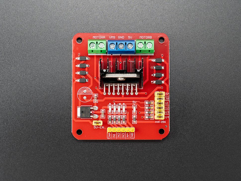
The L298N Motor Driver is a high-performance module designed for controlling motors for robotics and automation. It integrates a dual full-bridge driver capable of driving inductive loads like relays, solenoids, DC, and stepper motors. This driver allows for standard TTL logic level inputs and provides two enable inputs for easy on/off control.
Specifications
Detailed Specifications:
- Input Voltage (VMS): 6 to 35V
- Current (Per Channel): 2A
- Logic Voltage: 5 to 7V (internal LDO outputs 5V when enabled)
- Maximum Driver Power: 20 to 25W
- Sensing Voltage: -1 to 2.3V
- Dimensions: 60 x 54 x 30mm
Pinouts
| VMS | Motor Power Supply 6V to 35V |
| GND | Ground |
| 5V | 5V is the logic voltage pin. It gives 5V output when the internal LDO is enabled using the 5V-EN jumper. We recommend keep the jumper connected. |
| MOTORA | Outputs of the Bridge A |
| MOTORB | Outputs of the Bridge B |
| ENA | TTL Compatible Enable Input: the L state disables the bridge A. Use PWM signal on this pin to control the speed of the motor. |
| ENB | TTL Compatible Enable Input: the L state disables the bridge B. Use PWM signal on this pin to control the speed of the motor. |
| IN1, IN2 | TTL Compatible Inputs of the Bridge A (5V Logic) |
| IN3, IN4 | TTL Compatible Inputs of the Bridge B (5V Logic) |
| CSA | Current sensing pin of the Bridge A. (Connected with a jumper) |
| CSB | Current sensing pin of the Bridge B. (Connected with a jumper) |
| U1, U2, U3, U4 | Pull-up resistor pins. (Connected with a jumper) |
| 5V-EN | Connected with a jumper, enables the internal LDO to output 5V. |
Connections & Code
Power
- VMS: Connect it to a 6V to 35V power supply w.r.t the voltage rating of the motor.
- GND: Connect it to the power supply ground. Make sure you tie all the GND ground pins together.
- 5V: 5V is the logic voltage pin. It gives 5V output when the internal LDO is enabled using the 5V-EN jumper. We recommend keep the jumper connected.
Signal
Connections for Arduino UNO
- ENA: Connect it to Pin ~9
- IN1: Connect it to Pin 8
- IN2: Connect it to Pin 7
- IN3: Connect it to Pin ~6
- IN4: Connect it to Pin ~5
- ENB: Connect it to Pin ~3
Code
/*
MOTORA    IN1   |   IN2   |   ENA
------------------------------------
Forward   HIGH  |   LOW   |   255
------------------------------------
Reverse   LOW   |   HIGH  |   255
------------------------------------
STOP      LOW   |   LOW   |   0
------------------------------------

MOTORB    IN3   |   IN4   |   ENB
------------------------------------
Forward   HIGH  |   LOW   |   255
------------------------------------
Reverse   LOW   |   HIGH  |   255
------------------------------------
STOP      LOW   |   LOW   |   0
------------------------------------
*/

// Motor A, Left Side
const unit8_t ENA = 9
const unit8_t IN1 = 8
const unit8_t IN2 = 7
// Motor B, Right Side
const unit8_t IN3 = 6
const unit8_t IN4 = 5
const unit8_t ENB = 3

void stop(){
  digitalWrite(IN1, LOW);
  digitalWrite(IN2, LOW);
  digitalWrite(IN3, LOW);
  digitalWrite(IN4, LOW);
  analogWrite(ENA, 0);
  analogWrite(ENB, 0);
}

void moveForward(){
  digitalWrite(IN1, HIGH);
  digitalWrite(IN2, LOW);
  digitalWrite(IN3, HIGH);
  digitalWrite(IN4, LOW);
  analogWrite(ENA, 255);
  analogWrite(ENB, 255);
}

void moveReverse(){
  digitalWrite(IN1, LOW);
  digitalWrite(IN2, HIGH);
  digitalWrite(IN3, LOW);
  digitalWrite(IN4, HIGH);
  analogWrite(ENA, 255);
  analogWrite(ENB, 255);
}

void increaseForward(){
  for (int i=0; i<256; i++){
    digitalWrite(IN1, HIGH);
    digitalWrite(IN2, LOW);
    digitalWrite(IN3, HIGH);
    digitalWrite(IN4, LOW);
    analogWrite(ENA, i);
    analogWrite(ENB, i);
    delay(20);
  }
}

void setup() {
  pinMode(ENA, OUTPUT); //ENA Enable Pin
  pinMode(IN1, OUTPUT); //IN1
  pinMode(IN2, OUTPUT); //IN2
  pinMode(IN3, OUTPUT); //IN3
  pinMode(IN4, OUTPUT); //IN4
  pinMode(ENB, OUTPUT); //ENB Enable Pin
}

void loop(){
  stop(); // Stop DC Motors
  delay(3000);
  moveForward(); // Drive DC Motors Forward
  delay(3000);
  moveReverse(); // Drive DC Motors Reverse
  delay(3000);
  increaseForward(); // Drive DC Motors 0 to 100 Forward
  delay(3000);
}
Opps
Sorry, it looks like some products are not available in selected quantity.
Reviews
No reviews have been written for this product.