


Overview
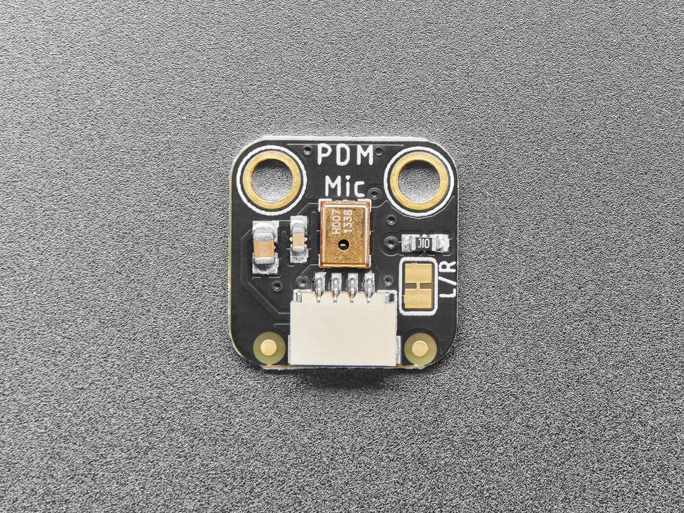
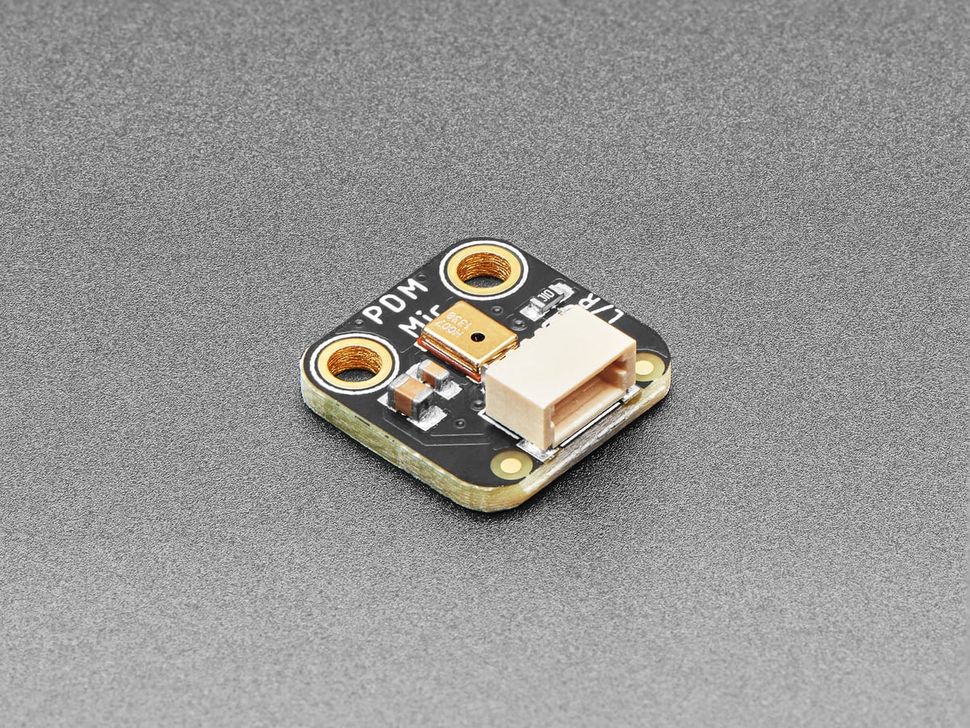
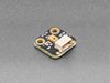
The Adafruit PDM MEMS Microphone Breakout Board lets you capture high-quality audio without relying on analog inputs or external ADCs. Instead of producing an analog signal, this microphone outputs 1-bit digital audio using Pulse Density Modulation (PDM), a format widely used in commercial electronics but less common in hobbyist projects.
This breakout is ideal for projects built around 32-bit MCUs that already include PDM hardware support, such as the nRF52 family, ESP32 variants, and many SAMD and RP-series boards. If your platform supports PDM, audio capture becomes efficient, low-noise, and highly reliable.
Unlike analog or I2S microphones, a PDM microphone outputs a high-speed stream of digital bits. The microphone is driven by an external clock (typically between 1 MHz and 3.25 MHz), and the data line produces a pulse stream where the density of 1s and 0s represents the audio waveform. With proper filtering and decimation—usually handled by hardware peripherals or libraries—you can reconstruct clean audio samples with minimal processing overhead.
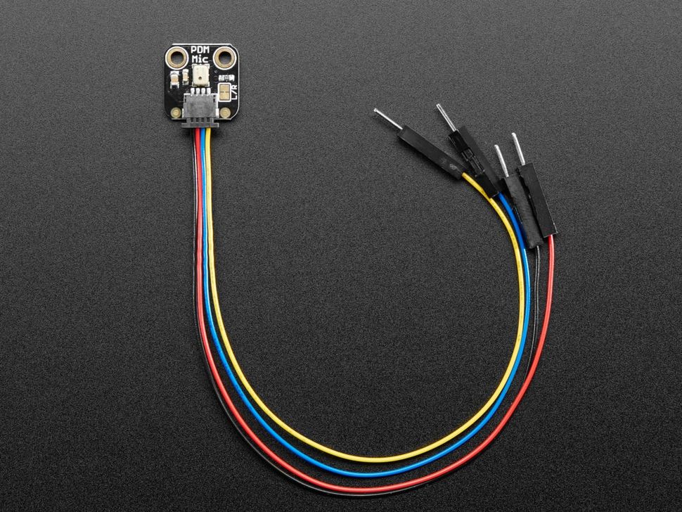
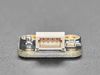
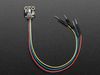
This version includes a JST SH 4-pin connector carrying power, ground, data, and clock signals, allowing you to connect the microphone remotely using JST SH cables.
Specification
Technical details for Adafruit PDM MEMS Microphone Breakout Board with JST SH Connector
| Specification | Details |
|---|---|
| Microphone Type | MEMS Digital Microphone |
| Audio Output | PDM (Pulse Density Modulation), 1-bit digital |
| Required Clock | External clock, 1.0 – 3.25 MHz |
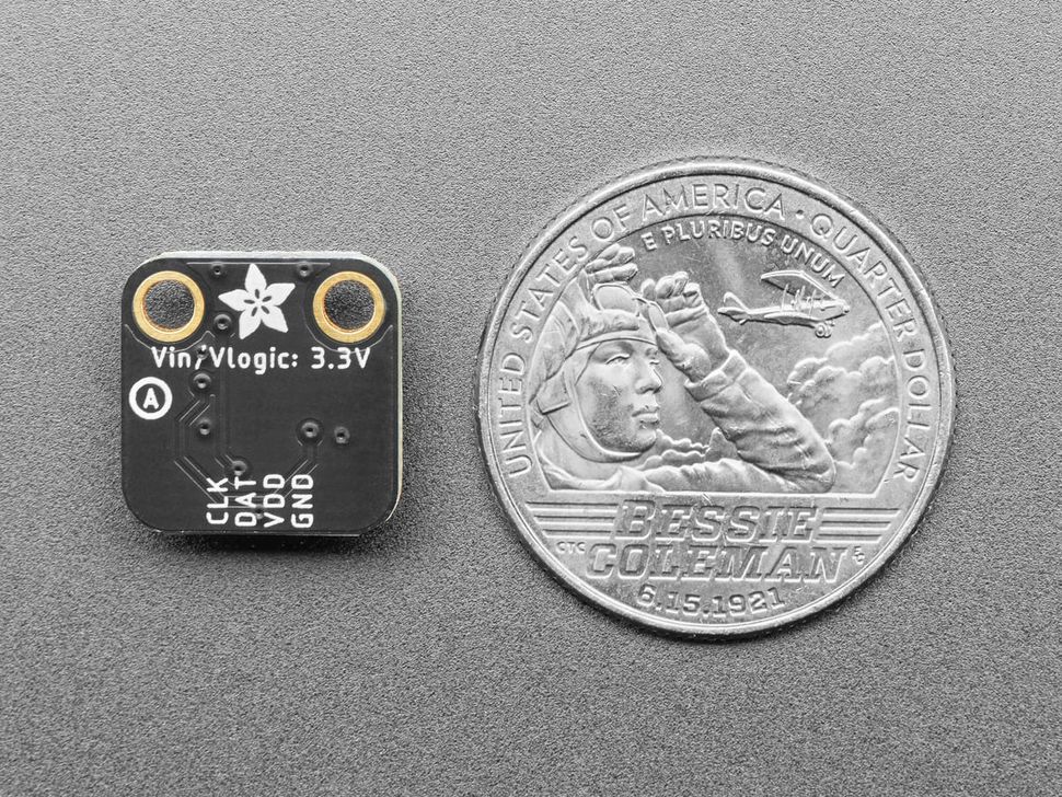
| Operating Voltage | 1.8 V – 3.3 V |
| Current Consumption | Approximately 0.6 mA |
| Signal-to-Noise Ratio | 61 dB |
| Sensitivity | ~ 26 dBFS |
| Connector | 4-pin JST SH (3V, GND, DAT, CLK) |
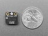
| Board Dimensions | 14.0 mm × 14.0 mm × 4.5 mm |
| Weight | 0.7 g |
| Assembly | Fully assembled and tested |
| Included | 1 × PDM MEMS Microphone Breakout Board |
Pinout
Pinout guide
| Pin | Description |
|---|---|
| 3V | Power supply input for the microphone. Supports 1.8V–3.3V operation (typically powered at 3.3V). For best audio performance, use a low-noise power source. |
| GND | Ground reference for power and data signals. |
| SEL | Left/Right channel select. Set HIGH to output data on the falling edge of the clock (Right channel). Set LOW to output data on the rising edge of the clock (Left channel). |
| CLK | PDM clock input. Requires a 1–3 MHz square wave generated by the host microcontroller. |
| DAT | PDM data output. Outputs a 1-bit pulse density modulated digital audio stream synchronized to the clock signal. |
Opps
Sorry, it looks like some products are not available in selected quantity.
Reviews
No reviews have been written for this product.